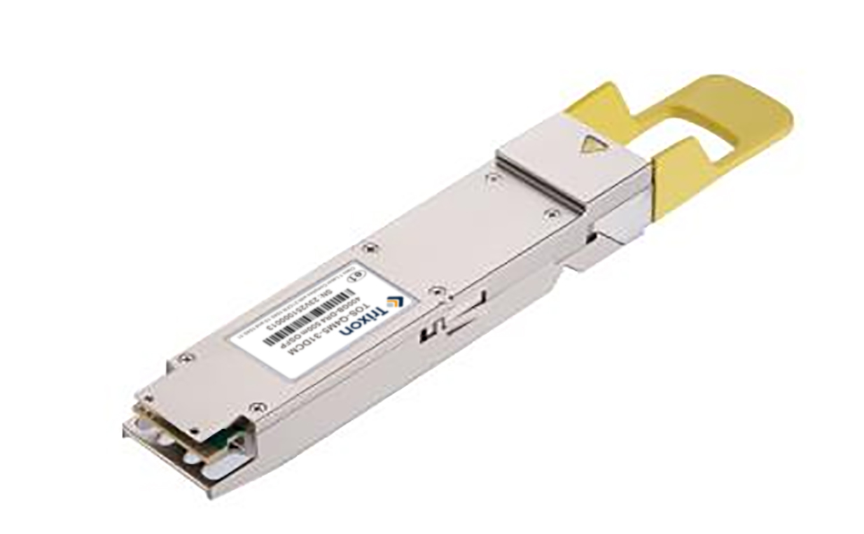
The core advantage of this optical module lies in its powerful high – speed transmission capability. It can achieve a transmission rate of up to 400Gbps. Through four independent channels, each channel transmits data at a rate of 100Gbps in parallel. This feature enables it to quickly transfer a large amount of data in an instant, significantly shortening the data processing and response time. In a data center environment, whether it is processing massive amounts of user data, conducting complex data analysis, or supporting cloud computing and artificial intelligence applications with extremely high real – time requirements, the 400G OSFP DR4 can handle them easily, ensuring the efficient flow of data.
Performance Specifications – Optical
Transmitter Optical Specifications
|
Parameter |
Symbol |
Min |
Typical |
Max. |
Unit |
Notes |
|
Wavelength |
λC |
1304.5 |
1311 |
1317.5 |
nm |
|
|
Side Mode Suppression Ratio |
SMSR |
30 |
- |
- |
dB |
|
|
Average Launch Power, each lane |
AOPL |
-2.9 |
- |
4.0 |
dBm |
1 |
|
Outer Optical Modulation Amplitude (OMAouter), each Lane |
TOMA |
-0.8 |
- |
4.2 |
dBm |
|
|
Launch power in OMAouter minus TDECQ, each lane |
TOMA-TDECQ |
-2.2 |
- |
- |
dBm |
|
|
Transmitter and Dispersion Eye Closure for PAM4 (TDECQ), each lane |
TDECQ |
- |
- |
3.4 |
dB |
|
|
TDECQ – 10log10(Ceq), each lane |
- |
- |
- |
3.4 |
dB |
|
|
Average Launch Power of OFF Transmitter, each lane |
TOFF |
- |
- |
-15 |
dBm |
|
|
Extinction Ratio |
ER |
3.5 |
- |
- |
dB |
|
|
Transmitter transition time |
Tr |
|
|
17 |
ps |
|
|
RIN21.4OMA |
RIN |
- |
- |
-136 |
dB/Hz |
|
|
Optical return loss tolerance |
ORL |
- |
- |
21.4 |
dB |
|
|
Transmitter Reflectance |
TR |
- |
- |
-26 |
dB |
2 |
Note 1: Average launch power, each lane (min) is informative and not the principal indicator of signal strength
Note 2: Transmitter reflectance is defined looking into the transmitter.
Receiver Optical Specifications
|
Parameter |
Symbol |
Min. |
Typical |
Max. |
Unit |
Notes |
|
Wavelength |
λC0 |
1304.5 |
1311 |
1317.5 |
nm |
|
|
Damage Threshold, each Lane |
AOPD |
5 |
- |
- |
dBm |
|
|
Average Receive Power, each Lane |
AOPR |
-5.9 |
- |
4 |
dBm |
|
|
Receive Power (OMAouter), each Lane |
OMAR |
- |
- |
4.2 |
dBm |
|
|
Receiver Reflectance |
RR |
- |
- |
-26 |
dB |
|
|
Receiver Sensitivity (OMAouter), each Lane |
SOMA |
- |
- |
Max(–3.9, SECQ – 5.3) |
dBm |
1 |
|
Stressed Receiver Sensitivity (OMAouter), each Lane |
SRS |
- |
- |
-1.9 |
dBm |
2 |
|
Conditions of stressed receiver sensitivity test |
|
|
|
|
|
|
|
Stressed eye closure for PAM4 (SECQ), lane under test |
SECQ |
- |
3.4 |
- |
dB |
|
|
SECQ – 10log10(Ceq), lane under test |
Ceq |
- |
- |
3.4 |
dB |
|
|
OMAouter of each aggressor lane |
- |
- |
4.2 |
- |
dBm |
|
Note 1: Receiver sensitivity (OMAouter), each lane (max) is informative and is defined for a transmitter with a value of SECQ up to 3.4 dB.
Note 2: Measured with conformance test signal at TP3 for the BER = 2.4×10⁻⁴


